Showing posts with label My Robots. Show all posts

Friday, September 30, 2022

AMR-One. 05 Project Management Plan

This is the fifth on the series of posts about the AMR-One Project. Today it is time to talk about what is a Project Management Plan, how to prepare it, and its application to the AMR-One project.

The Project Management Plan is defined as the document that describes how the project will be executed, monitored, controlled, and closed.

But... we already talked about it in my previous post The Project Management Plan. But the important thing is how you prepare it and why. For that, I used the AMR-One Project example and prepared the following video that I hope you like:


Tuesday, August 30, 2022

AMR-One. 04 Work Breakdown Structure (WBS)

This is the fourth on the series of posts about the AMR-One Project. Today I will talk about the Work Breakdown Structure tool as a way to get the tasks of a project.


The concept

Once we have somehow the scope, requirements, or definition of what we are going to do, we could prepare the Work Breakdown Structure (WBS).

The Project Management Institute (PMI) PMBOK defines the WBS as a “deliverable oriented hierarchical decomposition of the work to be executed by the project team.”

Basically is an iterative process that takes one large work product, and breaks it down into smaller, manageable work packages.

In a WBS such elements are the items that are estimated in terms of resource requirements, budget, and timing


WBS applied to AMR-One Project


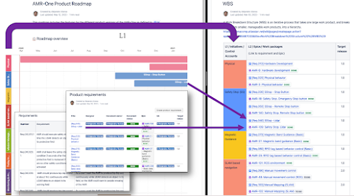
In the case of AMR-One, I made a simplification of the process, aligning the Product Roadmap, the Requirements, and WBS.

So in the WBS I added all Initiatives from the Roadmap as L1, and the Features or Epics as L2. Also I added one column to define the version of the product where these Epics will apply.


WBS related to Roadmap and Requirements


I didn’t split it into more levels as in this way it is quite aligned with the requirements already defined.

Now from here, and having the architectural approach mentioned in the previous video, we could start identifying atomic tasks within each Epic. This is work to do with the technical team, identifying dependencies, resources, time, and cost estimation.


Epics decomposition in atomic activities


And that is all so far. 

In the next post, I will explain to you how to prepare a good Project Plan. It is not only to have a plan of tasks, time, and costs. It is much more than that!

See the following video for more details:


Friday, July 29, 2022

AMR-One. 03 Architecting the solution

This is the third on the series of posts about the AMR-One Project. Today I will talk about architecting the solution.

In the previous post I described the requirements, so we know now what are the functions that the system should accomplish. But before defining the tasks to accomplish these requirements, we need to have an idea of how are we going to build the solution. For that, some people tend to create more technical requirements, in the language of the developers. I prefer to spend some time working on a pre-design of the whole system, from the mechanical, electrical, and software sides, involving representative people from each of the disciplines. It is essentially an iterative process, but having a basic architecture already opens minds to understand the tasks needed to build the system. 

When we have this general pre-design of the system, we could go further on the class definition for SW, materials for mechanics, or technologies for hardware.

Let's see as an example how this architecture has been defined in the AMR-One project.


The AMR-One case

As we saw in the episode about the roadmap, there are at least two versions of the product, with different functionalities. But we will consider the mechanical, hardware, and software approach for both versions 1.x and 2.x.


The mechanical approach

The mechanical approach starts with an overall analysis of the kinematics of the needed system, then continue with some freehand sketches and then with some draft ideas using some computer tools, but not going in deep on the design.

The hardware architecture

The hardware and electrical architecture define the components (sensors and actuators) but what is more important, helps to define the processing systems and the functions assigned to each of them. (click on the image to see it bigger)


HW architecture


We define 4 processing systems: 

  • Safety PLC (Flexisoft)
  • Low-level controller (LLC)
  • High-level controller (HLC)
  • Cloud base system

Going a bit further on the functions assigned to them we have that:

  • The Safety PLC is responsible for ensuring the safety measures are executed reliably. It uses several inputs (Safety Lidar and safety stop buttons) to determine when there is a dangerous situation and the system should stop. There is therefore a program inside this PLC to ensure this behavior.

  • The Low-Level Controller (LLC) is responsible for the Low-Level functions, which are the following:
    • Sensory reading
    • Traction motors PIDs controls
    • Velocities (linear and angular) conversion into inputs for the PIDs controls
    • Magnetic guidance
    • RFID tags reading and execution of actions
    • Pinhook control
    • Buzzer control for warnings
    • Device HMI data
    • ROS publisher to connect with HLC/Cloud Monitoring
    • ROS publisher/subscriber to connect with HLC/ROS navigation (AMR-One v2.0)

  • The High-Level Controller (HLC) is responsible mainly for:
    • Communication with the LLC
    • Communication to the cloud
    • User interface (AMR-One v2.0)
    • Localization, navigation, and mapping based on ROS (AMR-One v2.0)

  • The cloud-based processing system is not described in the hardware architecture because it would not require additional hardware from us.

The software structures

As mentioned, there are four processing systems, each of them with programs inside. 

The structures are quite self-explanatory. Only to mention that the items with yellow background correspond to v2.0 of the project and the rest correspond to v1.0 (click on the images to see them bigger)


See the following video for more details:


Now we know how to approach the solution and we are prepared to work on building a Work Breakdown Structure to define the Epics and tasks of the project, but this will come in the next post.

Monday, June 13, 2022

AMR-One. 02 Product Requirements

Today I will talk about "Product requirements”, from a conceptual point of view, and how they have been handled under the AMR-One Project, where an autonomous mobile robot for the industry is developed.


The concept

Requirements Engineering is one of the processes of Systems Engineering, that is focused on defining, documenting, and maintaining requirements. 

In the Waterfall Model, requirements engineering is presented as the first phase of the development process while Agile Methodologies, like Scrum, assume that requirements engineering continues through the lifetime of a system.

Basically, a requirement is a singular documented need that a particular design, product, or process must be able to perform. 

Once all stakeholders are aligned, the requirements serve as a compass, providing clear direction toward a product's purpose while creating a shared understanding among business and technical teams.


The steps

The steps to follow with the requirements are in summary:

  1. Eliciting and expressing requirements (getting the Requirements from the client)
  2. Prioritizing requirements, for example in the form of:
    • Must be done
    • Should be done
    • Could be done
  3. Analyzing requirements to ensure they are complete, clear, and consistent
  4. Analyzing also requirements from the technical point of view to ensure they are feasible in terms of time, cost and execution.

Types of requirements

When defining requirements it is good practice to cover several types of requirements, like:
  • Business requirements (Define why the product is needed)
  • Business rules (budget, policies or regulations, brand uniformity requirements,…)
  • User Requirements (what tasks the users can do with the product)
  • Functional Requirements (describe what the product should do)
  • Non-functional Requirements (describe how well a product must perform)
  • External interfaces 
  • Physical settings
  • Development constraint


In the following video, you could see this more in detail and how requirements are applied to the AMR-One Project, where an autonomous mobile robot for the industry is developed:


Tuesday, May 17, 2022

AMR-One. 01 Product Strategy and Roadmap

This is the first on a set of posts about the project AMR-One. 

AMR-One Project's scope is the development of an autonomous mobile robot for the industry. The set of posts covers not only the technical part but also project management and strategic concepts.

In this post we will mention the strategic part of the product, talking about the Product Strategy and Product Roadmap.

A Product Strategy is a high-level plan that defines your product goals throughout its life cycle and how it will support the organization’s goals. The product strategy will also answer who the product will serve and how it will benefit them.

These plans are then brought to life on the roadmap.

A Product Roadmap is a plan of action for how a product or solution will evolve over time. Product owners use roadmaps to outline future product functionality and when new features will be released.

To build a roadmap, product owners should consider market trajectories, customer value propositions, strategic goals, and effort constraints. Once these factors are understood, the product owner can work with their team to start prioritizing initiatives and epics on the roadmap.

The roadmap should be updated as often as necessary so that it can remain an accurate source of truth.

Having that roadmap we should go ahead with the Product Lifecycle Management, which is the process of managing the entire lifecycle of a product from its inception through the engineering, design, and manufacture, as well as the service and disposal of manufactured products.

See my previous post: 5 tips on ... Product Strategy & Product Roadmap

See the following video on how these concepts are applied to the AMR-One project:


Sunday, May 15, 2022

AMR-One. 00 Introduction to the AMR-One Project

This post is the introduction to the AMR-One project series, a set of posts and videos on how to plan, manage and execute a technical project as well as on how to technically develop an autonomous robot.

The AMR-One project objective is to develop a prototype of an autonomous mobile robot for the industry, as a personal project, with some basic characteristics:

  • Rotational base with damped traction system
  • Safety system
  • Pinhook system to hook trolleys from the bottom and carry them.
  • Two navigation modes:
    • Magnetic band guidance with RFID tags control
    • SLAM based navigation using ROS
  • Cloud monitoring (over AWS)


High, this is Alejandro Alonso and I will be here, through this interesting trip, where we will explore the details of this fascinating project!

During the following posts I will cover:

  • The product strategy, roadmap, and product requirements (basic to have good focus and scope definition).
  • The project management aspects, including
    • The project management plan (rules on how to manage the project)
    • Work breakdown structure (tool to identify the tasks)
    • Planning from an agile perspective, including the Gantt and dependency graph as well as backlog and sprints plan
    • Risk management, 
    • Cost and time control
    • Change management control, to approach correctly any change in the project
  • The technical design, covers:
    • The architecture of the system, both hardware, and software
    • Electrical design
    • Mechanical design
    • Software design
  • The manufacturing process, using modular structures and a few 3D printed parts

See the following introductory video.


I hope you enjoy this trip with me. Let’s make robots!

Monday, May 2, 2022

Cloud Monitoring for robots as IOT using AWS

AWS is a great Cloud Computing platform for many applications. Here I describe how I integrated ROS based mobile robots with IoT (IoTcore), Elasticsearch (Opensearch), and Kibana (OpenSearch Dashboards) to get Cloud Monitoring.


This video explains that under a personal project named "AMR-One" that covers the design and development of AMR-based solutions.

Link to the video: https://youtu.be/k_uQZ-rj-6M 


Related posts:

Sunday, January 24, 2021

Robotics Museums. A seed for passion

[3 minutes reading]

A good museum is not only a way to keep the history of our human evolution, but also could be an opportunity to discover inner passions. Also good Temporary Exhibition, Shows and Fairs are interesting ways to see more actual works.

Few weeks ago I visited The Robot Museum of Madrid (Spain) managed by my friend Daniel Bayon.  In this museum I have since 2017 several of the robots I worked on, like Sam, Melanie and Retrobot among others. 

This was not only a good opportunity to meet my friends and robots, but also to see again the collection this museum is offering. Some of them from the 80's that reminded me my origins in this passionate world.

Museums solely dedicated to robotics are not common yet. More common are the temporary exhibitions in different science museums around the world. Many times this exhibitions (either temporary or permanent) are linked to activities for kids related to STEM and robotics/programming workshops. Particularly I see it interesting, because the changes usually comes from the young people and interestingly, more and more is happening that young people, specially in STEM disciplines, wants to work only on what motivates and passionates them, not having any fear to loose a job if they don't like it. 

It is anyway not so easy, in one part because sometimes there are not enough job offers in what people loves, but other times is because people do not find their inner passion. Fortunately Robotics is one of those professions that are more and more offering good profesional opportunities. If we could unveil their passion at least for those who has robotics in their heart, then we will help the world to have a change done by passionate people and not just by workers.


Robotic museums around the world

This is a list of museums that I either visited or know they have at least a permanent section related to robotics. If you know more, just let me know and I will add to the list. Most of them are nowadays temporary closed due to Covid-19


Europe

USA

  • American Computer & Robotics Museum. Founded in May of 1990 by visionary collector George Keremedjiev. The museum exhibits span 4,000 years of human history, from original cuneiform tablets to the first personal computers, and include topics such as Artificial Intelligence, Quantum Computing, the Space Race, Cracking the Enigma Code, and more. (Bozeman, MT, USA)
  • Carnegie Science Centre. It has a permanent exhibition called Roboworld. (Pittsburgh, PA, USA)
  • MIT Museum Robot Exhibit. (Pittsburgh, PA, USA)
  • Computer History Museum. This museum, although devoted mainly to computers history, opened a permanent gallery on 1987 devoted to Smart Machine. (Mountain View, CA, USA)

Asia


Temporary Robotics exhibits

What is more common is to have temporary exhibits about robotics. Usually most of the Science Museums have this kind of exhibition, usually once every one or two years. Just to mention here are some of the past exhibitions done in some of these museums. Clic on the museum links below to access to those past robotics exhibitions:

MIT Museum (Cambridge, PA, USA), Science Museum (London, UK), Science + Industry Museum (Manchester, UK), Museum of Science & Industry Chicago (Chicago, IL, USA), Science Museum Group (UK), Vitra Design Museum (Germany), National Museum of Scotland (Scotland), V&A Dundee (Scotland), Hong Kong Science Museum (Hong Kong)


Sunday, June 3, 2018

ROS, for more than proofs of concept

It was not so far in time when I used to program robots using assembler language, a sort of machine code extremely close to the hardware of the machine. In those times programming a robot for complex functions, like navigating autonomously from one room to another was a difficult and time consuming project, that may take months for a team of people.

Robotics is evolving very fast as well as the open source movement. A really interesting outcome of both evolutions is ROS (Robot Operating System). ROS is an open-source, meta-operating system for robots, is a robotics middleware (i.e. collection of software frameworks for robot software development). It provides the services you would expect from an operating system, including hardware abstraction, low-level device control, implementation of commonly-used functionality, message-passing between processes, and package management. It also provides tools and libraries for obtaining, building, writing, and running code across multiple computers.

Nowadays it is possible to program a proof of concept for a robotics system in few days, thanks to ROS and all the open source, already available tools. Its integration with Gazebo Open Source Simulator is also a great help on the design and test of algorithms and behaviors.

Just as an example, let me share with you a development I did recently, using ROS. It took me about 10 hours to write on my own an application for a robot to work as a messenger, able to go to any room or location in a house  or an office to deliver goods. The function of the robot is very straightforward: You just put something on the tray of the robot and indicate in the touch screen where to deliver. Then the robot, using a 360 degrees laser scanner for detection of the environment and SLAM navigation technology, finds a trajectory to the required location. This development would have taken easily 6 months of work for a team of 5 people 10 years ago. Now you could have it in 10 hours of only one developer and with a hardware technology (robot platform, lidar, embedded computer) 


HERE you could also find all the documentation about the development of this solution.  In fact this documentation will be one of the chapter of my next book about ROS that I expect to publish soon.

But ROS is not only for developing a proof of concept, but real products for consumer and industrial market. I will talk more about it in future posts.

Thanks for the Open Source philosophy, thanks for the developers of Linux, the Open Source Operating System in which ROS works, thanks for all the hard work done by Willow Garage team for the development did of ROS and thanks to the incredible community of developers that share their knowledge and code for the Robotics evolution. This is the key factor of this time. We all are working to make the Robotics technology evolve, by sharing, for the art of sharing.

GIThub repository: https://github.com/aalonsopuig/MrMess_Robot.git

Reference:
[ Wikipedia. https://en.wikipedia.org/wiki/Robot_Operating_System ]
[ Ros.org http://wiki.ros.org/ROS/Introduction ]

Friday, January 27, 2017

Robots to the museum

Robotics is something I love since I was 10 years old. I worked in a lot of robots during my life. Some of them just for fun, and some of them for professional purpose, but I consider all of them as part of my life. Therefore it was really nice for me to agree with The Robot Museum of Madrid (Spain/Europe) to show some of my robots there as part of their permanent exhibition. 


Some of them, as shown in the picture above are:

  • SAM, a humanoid robot the size of a man, that could interact with people, talk in different languages and use computer vision to follow objects. Built in 2010.
  • Melanie-III, a walking hexapod robot able to walk on rough terrain and carry a payload 4 times its own weight (4Kg), like insects do. This robot won the Hispabot National price in 2004 and was used for research and development, being object of a publication in Springer 2005
  • Retrobot, A dancing robot I built just for fun along with my nephew Manuel. The goal of the project was to build a robot from spare parts of the 80's and 90's that could reproduce music from those years, and dance while shaking a maraca with its left arm, while extending its right arm to ask you for some money. Built in 2011.

Also, the museum will expose some other robots from my collection, including old robot arms and even figures of robots from SciFi movies.

It is nice to see that those robots will be available to the public in such a beautiful place.

The Robot Museum. Madrid

Sunday, December 27, 2015

Passion for Robotics. Greetings from my dear robots

With this post my robots and I would like to wish you all the best for 2016. I have worked on them during these last 15 years and it would be a pleasure for me to introduce you them.


Paul Inmoov (2015-2016)

This is based on the open source humanoid robot Inmoov designed by Gael Langevin. I am building it using a 3D printer, some motors and electronic devices. It is programed in Python over MyRobotLab framework. Very interesting robot indeed.
The purpose of building this robot is to test different humane-machine algorithms. The robot have a load of degrees of freedom. Just each arm has 10 servomotors and the head has 5 servomotors. The robot could talk while moving it's mouth, 2 cameras in it's eyes, that could be moved in any direction and the fingers of each arm could be moved independently.  

Mr. Drone (2015)

It’s an hexarotor drone I built using an open source PixHawk autopilot. The goal of building this drone was just to have a testing platform for different elements: gimbals, batteries, cameras, communications, software,...


CruiserBot® (2012-14)

CruiserBot is a modular robot for inspection, cleaning and disinfection of air ducts. We produced it in Quark Robotics by a team of three high qualified engineers under my direction.
It has a control console, a robot unit and accessories.
This robot was one of the three best robots, for this purpose, in the world. It’s microcontrollers were programmed in C 


RetroBot® (2011)

This was a robot I made for fun with my nephew. The purpose was to build a robot with products from early 80’s. For that we got a computer from the 80´s (Sinclair ZX-81) and other components from eBay.
The robot was able to move around, reproduce some sings from that age and dance while shaking maracas with his left arm. It also had a right arm with a grip.
View video


Sam (2008-2010)

Sam is a protocol humanoid robot designed to interact with people mainly in trade fairs. He is 1,5 meters tall, able to talk and show information at the interactive screen located on his chest. Therefore, he could inform people about the questions they want to, both speaking and through his screen. The robot moves around avoiding obstacles with his sensors, moves his head and arms and could shake hands with the people. He has an artificial vision system that allows Sam to recognize color objects. He has expression on his mouth, so could show the emotional status. Could be programmed to do any actions the customer desire. The robot was built by a team of three high qualified engineers, including myself, under my direction. 


Neptuno (2007)

This robot was a multipurpose base platform remotely controlled and used in an inspection project with thermal cameras.
It was designed and built by a couple of people, including myself.
The robot had two thermografic cameras covering 180 degree. It could support a weight of 150kg and move around during hours, as it has 8 batteries inside. The video signal was sent to a console unit with a monitor.
This robot concept was used for the development of the motion unit of Sam robot described above.
More information (In Spanish only)


Econobot (2007)

This was a project I developed with the aim of demonstrating that it was possible to make an educational robot with no money at all, by using recycled components from unused appliances and open source programming interpreter of LOGO language.
The robot had components from watches, DVDs, printers,... and was able not only to move, but to avoid obstacles with a double bumper


Melanie-III® (2004)

I made Melanie-III, an hexapod of 3 DOF/Leg, as an evolution of Melanie-II, described below. With the feedback from its 30 sensors for measuring physical values like joint positions, leg contact and current draw and its algorithms for rough terrain avoidance; the robot is able to walk over non-regular terrain maintaining a constant speed.


Melanie-II (2004)


Hexapod of 3 DOF/Leg I made in 2004. Was an evolution of Melanie-I, described below. It had some interesting capacities, like the direct programming (move legs manually and record it), the generation of movements by algorithms of waves displacement combined with inverse kinematics, or the capacity to walk on rough terrain. It was the winner of the National Robotics Contest Hispabot 2004 (Spain).


Melanie-I (2004)

Hexapod robot of 3 DOF/Leg I made in 2004.
The novel design of its legs allowed the robot to transport several kilograms on its body without excessive power overload.
This robot was originally tethered to a computer that was executing all the walking algorithms.


Brutus® (2004)

Brutus was born from the idea of building a modular robot, able to grow in capacity, to prove new experimental modules and navigation algorithms. The first version I made had wireless remote control of navigation, as well as a simple program for autonomous navigation, including some basic mapping of the obstacles surrounding the robot, by the use or a specific ultrasonic range analyser.


ST-Alexandrus (2002)
ST-Alexandrus was an hexapod of one degree of freedom by leg I made based on the structure of Stiquito. The locomotion system was based on muscle wires of Nitinol, a kind of shape memory metal alloy, used instead of motors.  Its mission consisted on moving avoiding obstacles with its antennas (bumpers).


Monty-Tuning (2002)

Monty-Tuning  was the "tuned/maked" version of the original robot Monty. I made and programmed it in Assembler, a language rarely used nowadays.
Monty was a commercial robot kit that allowed some configuration. It's electronics were very accessible, so some kind of electronics tuning was possible.
I have to recognize that this kit helped me to learn a lot on low level programming. The microcontroler used (PIC16F84) was a quite basic one and didn't have much memory. Because of that it was programmed in assembler, the closest language to Machine Code.


Reck® (1977)


The special thing of this robot is that I made it with 12 years old. Reck was a "robot" (to say something) very simple, it had a rear-wheels drive allowing only back and forward movements, a set of blinking lights at the eyes and sound electronic devices located at the mouth, capable of generating estrange sounds. The system was governed manually from a remote control box via cable, with switches and potentiometers.
Some years before, I started my first steps in the electronics world  with some educational games that I could apply in the simple pure analog design of Reck.
It was all of an experience, in a year (1977) were no Internet or personal computers were available to the general public yet. 
More information


Written by: Alejandro Alonso-Puig. HISPAROB Robotics Platform Vicepresident, IXION Industry & Aerospace MR Systems Manager and Quark Robotics Partner.

Sunday, April 5, 2015

Paul Inmoov get an arm


Paul is the robot I'm building right now, based on Inmoov, the 3D printed open source robot design by Gael Langevin.

I have finish building the right arm of Paul and this post is about it.

The arm is formed by more than 50 PLA plastic 3D printed parts, that took about 90 hours of printing time. All these parts are moved with 10 servomotors of different kind. Six of them are used for the hand (one motor per finger and another one for the rotation of the wrist), the other four motors are used for the movements of the arm. All the motors are connected to an Arduino Uno card. This Arduino card is connected via USB to a PC where I run MyRobotLab open Source framework. This Framework uses the Arduino board as an interface with the robot. As I mentioned in other previous post, MyRobotLab is a service based multi-threaded Open Source framework for robotics and creative machine control. It includes a lot of services for machine vision, video streaming, speech recognition, speech synthesis, motor control, arduino control and more. It is possible to develop new functionalities in Python Open Source language, so I prepared a Python program to do a demonstration of the robot functionality. The following video shows the robot and arm in action. The robot explain what he is doing, so no aditional explanation is needed.


Here is the Python Program used for it: Paul_GreetingsAndRArm.py

You could also watch a video I recorder showing how servos move the fingers. Each servo uses two tendons for mooving the fingers, one for closing it and the other for opening it. At this moment the tendons used, transfer to much power to the fingers. A next reasonable step would be to add some sort of tensioner or spring to each tendon, so the motors do not apply to much force to the fingers when they are used to take an object. Also there is no way now to measure or limit the preasure applied by the fingers to the objects. A good option may be either to measure the currend draw of each motor, the tension of the tendones or use some sort of presure sensors at the fingers. A lot of things could be done to improve the capacities of the robot. The limit is the imagination.


Next steps: to build the left arm and the structure of the stomach.

Saturday, February 7, 2015

Building a 3D Printed Open Source Humanoid Robot

Some months ago I found an incredibly interesting robot project. It was Inmoov, design by Gael Langevin, a humanoid Open Source robot that anyone could print with a 3D printer. I had one of these printers, so I decided to go ahead with the job. After 100 hours printing time I got 38 pieces solely for the head, neck and trunk. Some more hours of work for assembling the different parts and here is the result: My robot Paul Inmoov

Six servomotors are responsible for the behavior of the head parts: Three for the eyes movement, one for the mouth and a couple of them for the pan and tilt movement of the neck. Also there are a couple of cameras in the eyes for stereo vision.

All these motors are controlled from an Arduino Mega 2560 board, located at the back of the robot. Its a board based on the Atmel ATmega2560 microcontroller. It has 54 digital input/output pins (of which 15 can be used as PWM outputs), 16 analog inputs, 4 UARTs (hardware serial ports), a 16 MHz crystal oscillator and a USB port.

This Arduino card is connected via USB to a PC where I run MyRobotLab framework. This Framework uses the Arduino board as an interface with the robot.

MyRobotLab is a service based multi-threaded Open Source framework for robotics and creative machine control. It includes a lot of services for machine vision, video streaming, speech recognition, speech synthesis, motor control, arduino control and more. It is possible to develop new functionalities in Python Open Source language


After some programming in Python and searching through several internet forums, I made Paul talk and say Hello World. Here you could see the video:


And here is the Python Program used for it: Paul_Greatings.py

Next steps: To build the arms and program new behaviors

Wednesday, July 11, 2007

Neptuno. El nuevo bebé de Quark Robotics

Neptuno es el nuevo robot teleoperado de Quark Robotics para inspección basada en visión térmica. Su sistema de visión está compuesto por dos cámaras de infrarrojos con lentes de Germanio que cubren 180 grados de visión. El robot, dotado de 8 baterías de 12v posee una gran autonomía y potencia, siendo capaz de desplazar hasta 150kg de peso sobre si mismo. La base del robot, denominada Barion, es multipropósito, pudiendo llevar sistemas de cámaras infrarrojas o cualquier otro elemento.

Robot Neptuno, de Quark Robotics
El robot utiliza sistema de suspensión basculante trasera para asegurar que en todo momento están las 4 ruedas en contacto con el suelo.

A continuación se pueden ver algunos vídeos sobre el robot y su sistema de visión:


Robot en funcionamiento


Visión infrarroja del robot (objetos calientes aparecen claros)

Andrés dándose un paseo sobre el robot

Friday, February 9, 2007

Sam, a protocol robot: The Bust

Sam is a protocol robot, for interaction with people. The robot has been made as a project of my company Quark Robotics and has a human aspect to ease the interaction with people.

Actually the bust is fully finished.

The robot has two cameras for artificial vision and video transmission. Its mouth could express happiness, annoyance, surprise and indifference. The robot could also speak by using a speech synthesizer with it produce a talking effect in its lips.

It's head could move in pan and tilt ways by using some mechanisms located in its neck.

An interactive screen in it's chest could show images, videos, menus, so people could select different options by pressing the buttons at the sides of the screen.

The robot is very adequate as calling object at congresses, trade fairs, expositions, talking about the goodness of the products of a company, while visitors could ask Sam for more details of the products by pushing it's buttons.

Although Sam bust is autonomous, we are building the rest of the body, that would give harms and movement to Sam.

Here you could see a demonstration video of Sam:


Friday, September 10, 2004

Melanie-III - Robust Hexapod Robot of 3 dof/leg for rough terrain

Melanie-III was developed by Alejandro Alonso on September2004. 

Melanie is an hexapod robot of 3 degrees of freedom by leg, that by the novel design of legs it has, can transport several kilograms on its body without electrical power overload.


Melanie-III is an evolution of Melanie-II, to which some interesting capacities have been added,

With the feedback from its 30 sensors for measuring physical values like joint positions, leg contact and current consumption and its algorithms for rough terrain avoidance, the robot is able to walk over non-regular terrain maintaining a constant speed (see Video "walking over stones" below), as well as adapt its gate to terrains with holes (see Video "Slatted surface walking" below).

Slatted surface walking

walking over stones

Moreover, its capacity to generate movements via direct programming makes it possible to use the robot for testing complex gaits or for using it as an animatronic.

The control of the robot is done from an external computer. A wireless link allow the computer and robot to be properly communicated at a distance up to 100 meters.

Technical characteristics of Melanie-III:

Mechanics

  • Size (cm): 33 x 31 x 22
  • Weight: 3 Kg
  • Structure of PVC and Aluminum
  • 6 Legs. 3 degrees of freedom by leg.
  • Design of legs optimized to diminish consumption and to maximize power 
  • Driven by radio control servos (Twelve of 3kgcm and six of 5kgcm)

Electronics

  • Servos control circuit with speed management.
  • I/O-1 circuit, with 28 A/D conversion ports and 8 digital I/O. All chips are controlled via I2C bus. Measurement of the position of the 18 servos taking the signal of their potentiometers. Measurement of the consumption of energy of the servos by measuring the voltage drop in resistances of ½ ohm. 
  • I/O-2 circuit, with 10 A/D conversion ports, 16 digital I/O and two RS232C ports. The complete circuit is controlled via I2C bus.
  • Contact sensors at the legs
  • 2 data transceivers for information interchange with the external computer.
  • Battery of 6v NiMH 3300mAh for the servos
  • Battery of 7,2v NiMH 1200mAh for the control electronics
  • Distance measurement infrared sensor located at the front and able to be oriented

Programming

  • Control program in PC developed in Visual C++ 6.0
  • Movement sequence recording via direct programming
  • Movements generation by displacement of three simultaneous waves and use of inverse kinematics algorithms.
  • Detection of obstacles on the ground and adaptation of the legs and trajectories to resolve it.
  • Detection of lack of ground (holes) and adjustment of gaits to avoid them while walking.

More information:

Saturday, April 10, 2004

Melanie-II - Robust Hexapod Robot of 3 dof/leg for rough terrain

Melanie-II was developed by Alejandro Alonso on April 2004. This robot won the Hispabot 2004 National Robotics Contest at Spain.


Melanie is an hexapod robot of 3 degrees of freedom by leg, that by the novel design of legs it has, can transport several kilograms on its body without electrical power overload. The tests in laboratory have shown their capacity to rise and to walk at least with 4'5kg of additional charge, twice its own weight.

Melanie-II carrying 4 bricks of milk

The version II that is showed in this technical report is an evolution of Melanie-I, to which some interesting capacities have been added, like the direct programming, the generation of movements by
displacement of waves combined with inverse kinematics, or the capacity to walk on rough terrain.

Melanie walking over rough terrain

There is a version III with superior capacities. Complete information could be obtained here: Melanie-III

Some basic characteristics that define Melanie-II are the following:

Mechanics
  • Size (cm): 33 x 31 x 20
  • Weight: 2.1 Kg
  • Structure of PVC and Aluminum
  • 6 Legs. 3 degrees of freedom by leg.
  • Design of legs optimized to diminish consumption and to maximize power 
  • Driven by radio control servos (Twelve of 3kgcm and six of 5kgcm)
Electronics
  • Servos control circuit with speed management, controlled via serial port.
  • I/O circuit, with 28 A/D conversion ports and 8 digital I/O. All chips are controlled via I2C bus. Measurement of the position of the 18 servos taking the signal of their potentiometers. Measurement of the consumption of energy of the servos by measuring the voltage drop in resistances of ½ ohm. 
  • Battery of 6v NiMH 3300mAh for the servos
  • Battery of 9v NiCd for the control electronics
  • Distance measurement infrared sensor located at the front and able to be oriented
Programming
  • Control program in PC developed in Visual C++ 6.0
  • Movement sequence recording via direct programming
  • Movements generation by displacement of three simultaneous waves and use of inverse kinematics algorithms.
  • Detection of obstacles on the ground by detection of the variation in the current consumption and adaptation of the legs and trajectories to resolve it.

In this work there will be mention to all the mechanical, electronic and programming aspects, as well as conclusions of the experience.

More information:


Wednesday, March 10, 2004

Melanie-I - Robust Hexapod Robot of 3 dof/leg

Melanie-I was developed by Alejandro Alonso on March 2004

Melanie is an hexapod robot of 3 degrees of freedom by leg, that by the novel design of legs it has, can transport several kilograms on its body without electrical power overload.


The version I that is in this technical report refers the simplest version of the implementation of the robot, in which the robot is connected to an external PC by serial port (RS232C) for its control by a Visual C++ application.

There is a version II with superior capacities. Complete information could be obtained here: Melanie-II

Some basic characteristics that define Melanie v1.0 are the following:
  • Size (cm): 33 x 31 x 12 
  • Weight: 2,2Kg
  • Six legs
  • Three degrees of freedom per leg
  • Driven by RC servos (Twelve of 3kgcm and six of 5kgcm)
  • "smoothed" Control of servos by using a driver with speed management.
  • Communication with master PC by serial port RS232C
  • Distance measurement infrared sensor located at the front and able to be oriented
  • Structure of PVC and Aluminum
  • Battery of 6v NiMH 3300mAh for the servos
  • Battery of 9v NiMH for the control electronics
  • Control program in PC developed in Visual C++ 6.0
  • In this work there will be mention to all the mechanical,electronic and programming aspects, as well as conclusions of the experience.
More information:


Monday, February 2, 2004

Brutus v1.0. Rough terrain experimental robot

I made Brutus with the idea of building a modular robot, as a platform to prove new experimental modules.

The version 1.0 that is in this technical report refers to the simplest version of the implementation of the robot, in which it has wireless remote control of navigation, as well as a simple program for autonomous navigation.

Alejandro Alonso with his robot Brutus

Some basic characteristics that define Brutus v 1.0 are the following:

  • Size (cm): 120 x 85 x 50
  • 4 wheels 
  • Two electrical DC motors with good torque attached to the rear wheels
  • Rear suspension
  • Front steering controlled by a good torque servo
  • Front sonar with controllable orientation 
  • Shock Absorber (Fender/bumper) at the front with electronic shock detection
  • Onboard computer (Pentium) with control program in Visual C++
  • Module "Russian" for the management of the robot devices
  • Wireless communication WIFI with other external computer
  • 3 batteries of 12v
  • System fully controlled via I2C bus


In this work there will be mention to all the mechanical, electronic and programming aspects, as well as conclusions of the experience.

GIT (Repository)
Technical Report (.PDF)  <--- In Spanish. Not translated to English yet
"Brutus" program in Visual C++ (.ZIP)
Additional Pictures (.ZIP)